Solar Car: Rebuild (part 2)
- Role:
- Brakes & Steering Lead
- Date:
- 2025 - 2026
Part 2 of 2 in the Solar Car Series
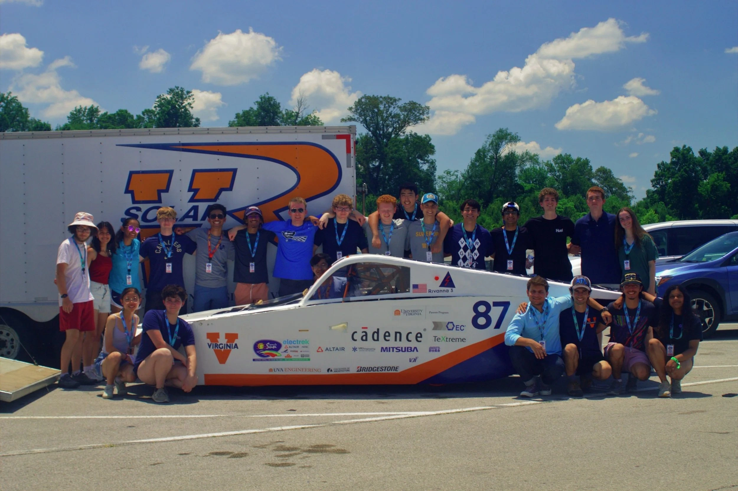
In Solar Car: Designing and Building a Custom Vehicle, I covered my first three years on the team across several subteams, culminating in our failure to qualify at the track. This page covers my senior year, when I led the Brakes & Steering subteam to redesign the vehicle's mechanical systems and prepare it for another attempt.
In my final year on the Solar Car team, I took on a leadership role as the Brakes & Steering Lead. Having narrowly failed to qualify at the track the previous year, I was motivated to address the root causes of our mechanical issues. Over the course of the year, I led a team composed mostly of first-year students to redesign the steering and braking systems while mentoring them through CAD, FEA, and hands-on manufacturing.
We rebuilt much of the vehicle’s mechanical systems around improved driver ergonomics, steering stability, serviceability, and reliability. This included a telescoping hexagonal steering shaft, redesigned brake plumbing and pedal assemblies, and a custom linear ratchet-and-pawl handbrake. At our end-of-year track event, the rebuilt vehicle passed the dynamic steering and braking tests and demonstrated substantially greater stability under hard braking and cornering.
1. Start of Year Planning
I kicked off the year by authoring a detailed write-up of the technical, ergonomic, and organizational problems I had observed during the previous season. I used it to define our priorities, budget requests, subteam organization, and set hard project deadlines to keep us on track. I also decided how to accept new members, evaluating them for the best subteam to take advantage of their strengths.
My team consisted mostly of first-year students who were hoping to gain hands-on experience, just as I had during my first year. My goal was to get them quickly up to speed and to have ownership over the projects they worked on while I kept the bigger picture in mind.
- Onboarding and Workshops: I spent the first several weeks creating CAD tutorials, presentations on fundamentals of vehicle dynamics, and exercises modeling real parts
- Team Structure: For each sub-project, I paired students into smaller groups tasked with brainstorming, drafting CAD models, 3D printing prototypes, and generating manufacturing plans.
- Managing the Projects: I acted as the main reviewer—validating calculations, suggesting improvements, and ensuring individual parts integrated with the larger vehicle.
2. Vehicle Dynamics: Correcting Weight Distribution
The single biggest handling issue we observed during track testing the previous year was severe oversteer, which we attributed mainly to the vehicle’s 70% rearward weight bias. Because our chassis and aerobody geometries were fixed this year, we couldn’t shift heavy components like the battery pack or driver seat further forward.
To address this without rebuilding the entire vehicle frame, the other leads and I decided to shift the rear contact patch rearward by converting the rear suspension from a double-wishbone to a custom trailing-arm suspension.


While the suspension team worked to manufacture the new components, I advised the geometry changes and completed physical integration of the components with the chassis and brake lines. Shifting the rear axle back alongside new shocks and stiffer rear springs brought our weight distribution from 70% rear to 55% rear / 45% front. During track testing, the vehicle instability we had observed during hard braking and turning the previous year was substantially reduced.
3. Steering System Redesign
I oversaw a complete redesign of our steering assembly to reduce mechanical play and improve driver control and comfort.
Telescoping Steering Shaft
- The Problem: The old solid steel shaft was excessively heavy, lacked positional adjustment, had significant slop, and obstructed the driver during emergency egress.
- The Solution: We designed a telescoping hexagonal steering shaft using hollow steel tubing. The hexagonal profile transmitted steering torque like a wrench while reducing the shaft’s calculated mass over 30%. A spring-loaded locking pin allowed 16 in of axial adjustment for driver clearance, while a coupler was welded on the steering wheel end, and a splined shaft cut and welded to the opposite end to connect to the U-joint.
- Shaft Support: To secure the shaft while allowing both rotation and sliding, we welded a triangular tubular steel brace directly to the chassis with 3D-printed nylon bushings featuring a hexagonal bore and circular outer surface.


Steering Linkages
- Steering Arms: The previous 1/8“ sheet metal arms flexed noticeably under load. We welded structural gussets onto the arms to improve stiffness.
- A Design for Next Year: I designed a new set of hollow steel uprights that were lighter and easier to attach components to, and steering arms that were longer for lower steering effort. Unfortunately, we ran out of time to manufacture the uprights, so I tapped threaded holes into the existing aluminum uprights to attach a simpler set of redesigned steering arms to. However, I was not confident that the threaded inserts provided sufficient strength, so we retained the existing steering arm configuration rather than relying on them for the final design.
- Clearance Issues: Machined precise aluminum spacers for the rack-and-pinion and brake rotors to eliminate contact points on the steering rack boot and the wheel hubs.
- Steering Stops: Designed physical chassis stops to limit rack travel before tires could contact the lower control arms.

Future Improvements
While the telescoping shaft significantly reduced play and improved driver comfort and ease of egress, the design still had shortcomings. The 3D-printed nylon bushings were susceptible to warping from moisture, and the locking pin was occasionally difficult to operate because of its position relative to the driver. Switching to CNC-machined bronze bushings would prevent warping and could improve durability, while relocating or redesigning the locking mechanism would make adjustment and emergency egress easier.
4. Braking Systems Redesign
My goal for the braking system was to make braking more ergonomic, easier to maintain, and more reliable.
Switching to Hard Line Brake Plumbing
- Hard Line Routing: Replaced long, tangled soft lines with copper-nickel hard lines cut, bent, and flared by hand, and made-to-length braided stainless steel 3AN lines to reach the calipers. This setup is much neater, more durable, and keeps the brake lines clear of moving components.
- Chassis Mounting: Secured hard lines to the chassis using rubber-lined P-clamps and welded bulkheads rather than zip-ties, protecting lines from chassis vibration and chafing.
- Pressure Sensing: Integrated two inline LDM899TP hydraulic pressure/temperature sensors to set the brake light activation threshold and evaluate the balance bar bias against my pressure calculations.
- Knowledge Transfer: Led workshops on proper bleeding techniques for more members to learn how to remove air bubbles in the brake lines.
Better Pedal Assemblies
- Ergonomics: The original floor mounted brake pedal was stiff and uncomfortable for drivers with shorter leg lengths. I decided to invert the pedal into a swing-mount configuration with a welded sheet metal plate. I had drivers of varying heights test the pedal to get the right distance. The new configuration was much more comfortable for drivers and provided better pressing leverage.
- Mounting Plate FEA: Ran structural FEA on the pedal mounting plate to evaluate its stiffness under expected driver loading. During testing, the plate flexed more than the simulation predicted, showing that our assumed loading was too low and that additional support was needed.
- Designing for Service: For the accelerator plate, I changed the attachment method to avoid requiring the removal of other parts for access, and replaced hard to reach nuts with threaded inserts. I also changed the bolt positions on the brake plate to make the nuts easy to get a wrench on.
Linear Ratchet and Pawl Handbrake
Our handbrake had many issues, from leaks, failure to hold the vehicle in park, and lack of adjustment. We decided to replace it with a custom linear ratchet and pawl mechanism attached to a new handbrake with a return spring and reset handle. The new design was adjustable, locked firmly in place, and integrated into the new hard lines with no leaks and a firm feel.
We also mounted the handbrake to new brackets welded to a chassis side rib. These brackets took up less space from the driver’s seat, and were far easier to remove than the previous floor-mounted model while placing the handbrake in a more natural position for the driver.

The mechanism worked reliably and provided smooth adjustment, but the linear ratchet was bulkier than a conventional circular ratchet-and-pawl with coarser adjustment. A traditional mechanism that used a button instead of a lever would have been more compact and ergonomic for the driver.
5. Track Testing
Across the team, we overhauled nearly every major vehicle system, including the software, battery pack, topshell, and mechanical systems. Due to funding challenges and logistical constraints, we decided not to travel to the national competition that summer. Instead, we rented a private racetrack to conduct our own validation testing for improvements to make to race the following year.
During testing, the vehicle passed all of the dynamic steering and braking tests we replicated from the previous year’s FSGP scrutineering. Drivers also reported that the car felt substantially more stable and easier to control than the previous year.
Unfortunately, our BMS had issues which capped our maximum current and made it difficult to gather as many miles as we would have liked, but we gained a much better understanding of the limitations of our designs.
My Takeaways
Leading a yearlong engineering design cycle was both challenging and very rewarding, and I learned a lot:
- Designing for Manufacturing & Maintenance: Making a model in CAD is simple; designing a part around available manufacturing methods while considering how it will be assembled and maintained requires much more thought.
- Delegating is a Skill: It’s tempting to try to do everything by myself, but having the patience to teach and empower newer members is the best way for them to learn and contribute effectively.
- Iteration Takes Time: Setting hard deadlines for testing forced us to identify problems much earlier, and having another cycle of iteration would have solved many of the challenges we didn’t get to this year.
- Working Style: I thrive in fast-paced projects where I can work closely with others, take ownership of ambiguous problems, and have the freedom to iterate on different approaches.
Overall, working on the Solar Car project alongside such wonderful people was some of my favorite time spent at UVA. I hope with all my future work to find a similar environment and put my passion into a similarly meaningful project.